
Chris Foss Phase 5 Glider Build April 2019
After what turned out to be a very successful and generally enjoyable Phase 6 build, the big question is what to have a go at building next?
Well I decided on a Chris Foss designed aerobatic slope soarer called a Phase 5. Its 73'' span is larger than the Phase 6 and comes complete with a built up wing, flaps and ailerons in its original design.


Here is the maiden flight of my Phase 5 (build log below)

Phase 5 (as built to date) 29th May 2019
Having already received the laser cut rib set that I purchased of eBay we are nearly getting to a stage I could think about buying in wood to start the build. I am not intending to rush this build (famous last words!) but to take my time as this build will need a lot more thought and understanding for my little brain to understand what's printed on the plan and then to decipher the details before cutting and gluing, so please bear with me.
As ever I appreciate the feed back form Russel and my other readers, so please be kind with your comments and help as things progress. No abuse as I am a delicate trainee model builder.

Big pile of wood has arrived!

Within the Phase 5 rib set I purchased online came 4 servo frame / mounts that were laser cut for a very rare Turnigy Servo. Eventually found someone who had these servo's in stock. Had to buy them while they where still available. It wouldn't have been my first choice of servo manufacturer but the Savox HS85MG's that I had used in my Phase 6 wouldn't have fitted into the servo mount supplied.

I'm trying to build as per the Instructions (printed in 1978)
Item 1 - I cheated big time by purchasing a laser cut rib kit online, so I can miss Item1 out (Phew!)
Item 2 - Attach 1/4 x 3/8 t/e/ spar to 1/16 x 5/8 t/e sheet. I had to use my Balsa stripper (a first for me) to get a 5/8 section of 1/16 sheet. It seemed to go ok. Glued together and leave to dry!

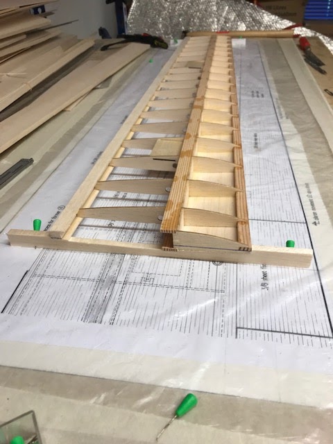
Russell kindly cycled all the way over to my place and spent some time walking through various questions I had about the Phase 5 build. The first problems I had was getting the leading spar (not lead edge) and trailing edge to stay in position. Both of these sit on packers but you can't pin through spruce very easily at the front and the T/E is only just resting on the corner of the 1/4 x 3/8 packers. Well Russell introduced me to wedges and other useful tips to aid the build. Because everything needs to be just right and ribs etc can be knocked or moved easily I though it would be a good idea to use Cyno to spot glue everything in situ. The first thing was to dry fit the ribs, Servo trays and top spa (which in fact will be the top as you build the wing upside down).
 |
| Dry fitting the ribs, spars etc...... |
 |
| Servo bottom tray neatly slots into wing ribs |
 |
| 3/8'' packers support the T/E |
| 1/2'' packers on L/E Spruce |


Item 3 -Check, check and triple check everything before I will glue anything. Note the back of the rib needs to sit square and evenly with the T/E and the sheeting underneath and this angle changes along the wing.

Item 4 (above) -So here we are with the ribs and front, top and bottom spruce spars glued using Cyno using a fine tip on the bottle that gives you precise spot glue location which wicks into and along the joint. As you will see later I should have glued the remaining 1/16 x 5/8 T/E sheet on at this point
Item 5 - Add 1/16th sheet spar webbing. Each individual section of balsa needs to be cut and sanded to shape to locate between each rib but remember to leave the 1/16th gap for the top and bottom leading edge sheeting. The grain of the balsa runs top to bottom
 |
| Measure the gap between the ribs and then the depth of the rib and there's the size of your balsa infil |
Item 6 - Glued the 1/16th strip along the LE and up against the ribs. This needed to be sanded to follow the form of the ribs to provide support and another gluing face for the balsa sheet.

 |
| This is the underside of the wing. LE Sheeting in place. No LE fitted as yet |
Cleaned the tips up and cut the spruce spars flush to the end ribs.


Have to go back to Item 4 - Forgot to glue the remaining 1/16 x 5/8 T/E sheet to bottom surface while upside down in the jig. I knew something was missing!


1/16 x 5/8 T/E sheet held in place using my soft pegs that apply pressure but (hopefully) doesn't damage the balsa sheet. They seem very good so far.
The next stage is to turn the wing over to repeat the process (Item 6) on the top surface.
Item 7 - For this Chris suggests you make some simple cradles for the wing tips. I made these by photocopying the root and wing tip section cut them through the datum line and stick these onto some 3/8 x 5/8 balsa sheet. Then simply cut out the rib section which left me with this...…

This is to make sure there isn't any twist in the wing. As long as the datum line marked on the wing root and tips and level with my cradles them the wing should be true and square.
Right onward - Here we are with the 1/16th strip being glued to the L/E of the upper surface (Item 6)

Here is the wing with the 1/16th strip sanded virtually all down to match the rib profile.


Right here we go for a weeks work. I said it was going to be slow and steady!
 |
| Top and bottom L/E skin glued on and now ready for the actual L/E |

Now there are holes conveniently positioned through the ribs to allow a 6mm straw. This will become your servo cable tubes later. Could I find plastic strews anywhere? - NO! So had to go eco friendly and fit sturdy paper straws which I feel will do the job well.

Now here's an interesting thing. The plan you buy from CF only details a right wing. I've been scratching my head how I was going to get the left hand wing detail from this. With other plans I have just turned the plan over and built the opposite wing from there but the paper quality is too good and there is no detail showing through on the reverse. maybe I could trace the right wing and use the reverse of the traced wing or even better I could take the plan to a print shop and get them to scan in the plan and then mirror print the plan for me - YES IT WORKS WELL !
£4.50 and I had a mirrored left hand wing in detail (of course all the writing was back to front but who cares) This saved me loads of time and effort!
I'm not going to repeat all the pictures and stages as the right wing for the left as its all exactly the same so wont bore you even more pictures than I have already. Just repeat each of the previous steps to build the left hand wing over a left handed plan.
I decided to glue the 1/4 x 3/8 leading edge to the right hand half of the wing on as I can't see from the instructions when this should be done. I can't think of any reason why not - so I've gone and done it as it seems the right thing to do.

A quick video update on where I am with the build.
Item 8 - Having nearly finished the second half of the wing, I decided to use my time and make the 1/4'' ply wing joiner. I traced around the exact size of the wing joiner on the plan. Transferred this to the plywood and cut it out accordingly.
  |
| My first attempt at the wing joiner was made exactly as the plan view on the plan. This is incorrect! (See Below) |

I now need to cut a hole through the No.1 rib to accept the ply wing joiner and glue into position (scary!).

Time to glue the two halves together.

The joint seems good and the wing in nice and straight and true


Item 9 - I am skipping Item 9 as I will be using a 4 servo wing and not the original bell crank system.
Item 10 - I have started Item 10 with the 1/8'' x 1/2'' ply plate (with the bolt hole pre drilled). I do think this should have been a 1/4'' x 1/2'' when you look at the cross section of the wing root. Here it details a different size than the written specification.


Top surface centre section sheeting glued on with hole cut (nearly) round for bolt head.
Decided to go in my own direction and fitted the top capping and the mid and end sheeting to add some additional strength to the wing to fit the wing servo's in place now and feed cables through so I can then sheet the underside.


Used tracing paper to get the exact size of sheeting I needed.
|
 |
| Did the job well. I'm happy with the underside centre sheeting |

After finishing the servo boxes and the final bit of sheeting the wing got a proper sanding, especially the trailing edge which was shaped to the top capping.
Really happy with the wing now!
I've been thinking hard on how I will get the 3/8'' sheet trailing edge finished to the correct angle i.e. triangular T/E shaped. Do I glue the centre section on and then shape to the correct size and angle or shape it first then glue it on. Well I think I got it right and sanded the angles and shape first so the top section of the wing matches the exact angle (well near enough) the trailing edge.


From a solid lump of 3/8 sheet you have to shape the flap / aileron


Ailerons pretty much finished, so next was to glue the unfinished wing tip to the wing.

The before & after shot of the tip

FUSELAGE
Fuselage: Item 1
Started by tracing the fuselage section and then tried to trace this onto the balsa but this didn't work very well. Ten tried putting pins in the corners or change of direction of the fuselage this sort of helped but between them I managed to get a shape onto my 3/16'' balsa sheet. I used a razor saw and slowly cut around the shape and it looks roughly right sort of shape (roughly). I then pinned it on top of another sheet and traced around as a pattern. I then should of cut around the second side with my saw but I tried to cut around the pattern side with a scalpel. Did it work? Mmmmmm??/


Clamped the two sides together and sanded down some of the indifferences. The bit around the wing seat wasn't right. Cut too much off. So just glue another bit on and sand down when dry to the right shape - correct!!

Well I have seemed to take ages faffing around to get two halves if fuselage the same shape. How difficult can it be? Well I've made it very difficult for myself. Anyway I'm finally happy the two sizes mirror each other. So hear they are..... clearly marked up 'Left' and 'Right'.

Now it's time to make the spruce longerons for the fuselage sides. Now another small error is that the instructions detail 1/8 x 1/2 spruce but in fact as the plan details its actually 1/8 x 3/8 spruce.
I carefully marked out each section and cut the required length and angle for each piece (hopefully) and used the right hand wing as a template for the left side. Remember to chamfer the rear spruce to just 1/16 (noted on plan) to allow the rudder cables some space when complete.

1/8 x 3/8 spruce and 3/8 balsa triangular longerons glued in to place.


Time to make the Formers 1, 2 & 3.
 |
| Formers sanded to match the fuselage sides so slightly different from the plan but by not a lot |

Two snakes fitted. One heavy duty one for the elevator (blue) and a thinner and smaller one (yellow) for the rudder.

slots cut into Former 2 to allow for the snakes


Bit the bullet and glued the two sides together in the jig. Different method to what is recommended in the Instructions.

The fuselage came out of the jig nice and square (I think) with no obvious banana thankfully!
Now it's time to glue the 1/2'' top sheet (inverted) over some 3/8's packers. Looks odd but hopefully will work.


Time to glue the sheeting on the underside starting of with the 3/8 section


Time to cut out the slot for the fin into the top 1/2 sheet.

Once this is done, take a deep breath and glue the back end fin to the fuselage.


Time for a dry run.

Here we have the two dowels that need gluing into the wing.

Then add the little plywood fairing over the top to cover the wing dowels


I thought it was going to be trouble but it went relatively easy.


Then I fitted the wing retaining bolt captive into a decent bit of plywood. The bolt now fits perfectly!
I spent a good bit of time filling in little chunks and scratches in the balsa with light filler.
The next job was to use my Poly C and some light weight glass to strengthen the bottom of the front and middle bays of the model. Probably doesn't need it but what the heck.
Decided to crack on with building the fin. Building it flat on the plan / board.
First of all I decided to have a go at the bell crank support box.


Plucked up the courage to glue the bell crank assembly together. The wire is as near to the horizontal as I can get it against the vertical sides.
One big issue was that the bell crank was a little stiff. All sorted out now!


Took it to Tim who removed the top section of balsa to have a look at what was going on. By doing this it eased the snagging and the bell crank now works well. Replace the balsa top and its working fine.
Been busy with the rest of the fin. Gluing in the triangular frame/sheet section to the front of the fin and the rudder post.

Phase 5 fin dry fitted onto the bell crank assembly
Here Is the fin and bell crank assembly fully glued and sanded smooth


Tail Plane
Now some confusion here (my lack of knowledge). The plan details the tail plane having two different sections of 3/8 Balsa sheet with the grain running in two different directions. First of all I thought I would make the tail plane by butting two pieces of 3/8 sheet together and gluing them together but the 'build it properly' voice came into my head, so after a lot of head scratching I think I have done it right but who knows. I have a block of 3/8 sheet with the grain running in different directions and I am awaiting the glue to dry and have to wait and see if it worked or not.


I'm sure there has got to be an easier job than cutting out in paper the wing template and gluing each half and then cutting each sheet to match the halved template in the direction of the grain and then gluing these two halves together??
Here is the results...…..


Now how do I cut out the 1/8 slots for the brass tube?
Here's a mock up of the tail as it is at the moment.

My 14g wire front tail plane wire doesn't fit the positioning on Chris's plan even though I used his bell crank. The rear wire is spot on but the front wire is behind the one positioned on the drawing.
As this is the case I decided to turn my tail planes over to the blank balsa side and mark the position of my wires. It seems to me that the positioning of these wires and the slots cut for the brass tube is very important.


I took a deep breath and cut out the slots for the brass tube.
Slots cut with a razor saw and the end of the slot drilled square.

Brass tubes cut to size and fit snugly into the slots. Works well with the bell crank!

Once the brass tubes have been set into the wings using spruce for the centre pivot point and balsa for the front slot. This front slot will need to be shaped a little later.
I glues a 1/8 square section all the way along the back of the all moving tail plane. This gave me something hard to sand up to and also will protect those exposed edges when moving the glider around. I did the same thing on the rudder too.

RC Equipment
Having basically finished the build its time for Tim to work his magic with kitting the Phase 5
out with its servo's etc.


The fuselage servo's have been fitted for the elevator and the rudder


Here is the underside of the wing with its chequered black and yellow design. To add contrast with the upper surface which will be yellow.


This one is for Russell...…


Good luck Paul.
ReplyDeleteThat is a very nicely finished example from Mike Brinkworth, I notice there are two bolts holding Mike's P-5 wing on, from which I deduce he has a two-piece wing (not shown on the plan, but a very practical adaptation). If you are going to follow suit you might want to think about the joining method before you start building.
To gather the materials for this kind of project I like to mark-up the plan with item numbers and fill in a spreadsheet.
I suggest you test those servos thoroughly before installation, HK used to stock them. I notice that iGull have not included servo mounts with their Quicksilver rib set (which I bought recently).
ReplyDeletePreformed servo mounts are a bit of a luxury, but there are many available including:
http://www.phoenixmp.com/acatalog/Wing_Servo_Mounts.html
For my Ridge Runt wing I have stuck Emax 12g MG servos onto ply plates with servo tape and glued bits of balsa around them for added security.
Any idea how I test the servo's before I use them? I assume I need a servo tester but do you need to put them under a load? Sorry, not a clue Russell!
DeleteA servo tester is convenient but not essential, it can be used for a 'soak' test to oscillate the servo continuously which is handy. But like many electrical gadgets servos either work or they don't, if they don't it will show up very quickly. Just make sure they all move smoothly, centre well and have the same amount of travel in each direction.
DeleteWhen HK stocked the TGY-113MG they had very mixed reviews on the website, but iGull assured me they used them all the time without issue...
Do you reckon I should return them and buy the Savox SH0255MG which are very much the same size but with a little more torque?
DeleteI don't know what the price difference would be, but for your peace of mind perhaps yes. I filed out the servo mounts which came with my PMP Stage 2 Mk II to suit similar (but cheaper) servos without any problem.
DeletePersonally, if I had already bought those servos to suit my Phase 5 rib set (I had planned to, but got distracted by another model project) then I'd use them.
Is there any chance Russell you might pop over one day (soon) if possible and talk me through a few things I need help with? I'm in Plumpton Green (any time that's good for you)
DeleteI'll talk to the Mrs, but I should be available at some point this weekend. I'll phone or text to confirm.
DeleteI have an idea for creating a plan for the right hand wing since C.F. has only drawn the left one. When you've finished building the first wing take the plan of the building board and tape it to the window, face out. The daylight will shine though enabling you to trace over the back of the plan with a pencil or pen. Lay the plan face down on the board and build a mirror image wing over your own drawing.
ReplyDeleteI built a Phase 5 a year ago it is by far my best glider. It greatly benefits from using four wing servos with modern radio that can mix the inner and out flaps in various ways. Two things I have learnt. 1 Plugging in all the leads for 6 servos can be tiresome. Currently I have the receiver mounted in the win GC area with 4 wing servos connected. Then I only have to plug in the rudder and elevators, one of which has a Y lead to the power source. I'm gong to build a better version with the JR connectors built into a forward locating tongue instead of the two dowels. 2 I have glassed the mid wing area for strength, this also helps the single wing bolt (which is perfectly adequate). I hope this helps you won't get a better flyer IMHO.
ReplyDeleteNow could be a good time to thread the servo wire drinking straws through the rib holes, before you add the centre sheeting.
ReplyDeleteThe cradles look good. You could cut the same lengths of 1/4 x 3/8 un-carved and glue them alongside the carved versions to allow the wing tips to nestle into the corners, but if you pin them down it's probably not necessary.
ReplyDeleteThanks Russell. I really appreciate your help and it's good to know I'm going in the right direction.
DeleteYou'll have to have a word with your mate Chris about that erroneous wing joiner outline. Did you mean 'drill through the No.1 rib' rather than the No.1 spar?
ReplyDeleteThanks Russell, I did mean No. 1 Rib and not spar.
DeleteAs you know the wing joiner shape defines the dihedral, or lack of it. If it is a snug fit between the spars it should taper slightly on the bottom edge so that when the wings are glued together up-side-down on a flat surface, the tapering wing ribs should give a small under-surface 'dihedral'.
DeleteThat is the usual routine on a 'kipper' slope soarer like this.
Welcome back Paul, I expect you're relieved to be in the peace and quiet of your office/workshop after your holiday.
ReplyDeleteThat all-moving tailplane with internal bell-crank arrangement always looked 'difficult' to me compared to the normal elevator setup - but you make it look easy! Well done.
Hi Russell. Its nice to be building again. The bell crank assembly hasn't been too difficult up to now but I have yet to glue it all together as I'm not sure how to glue it together but still keeping the 14g wire horizontal to the assembly. I need to figure this out. Glue it wrong and the tail plane will be wonky. Any suggestions?
ReplyDeleteI'm not sure (having never tackled this task)but:
ReplyDelete1. Ensure the holes are perfectly aligned with each other (i.e. drilled straight through)
2. Ensure the nylon bushes fit snugly into the holes in the plywood/spacers.
3. Build the plywood box squarely.
Then the tailplane support rod should be perpendicular to the fin post to which the box is glued.
Went for it Russell. The bell crank is a little stiff and I am not sure if there is anything I could do to free it up.
DeleteA squirt of WD40?
Yes, you could get away with WD40 I suppose. The proper answer is to rebuild the bell-crank box assembly using thinner spacers and paying extra attention to the alignment to ensure squareness. But at the end of the day, you only have to satisfy your own expectations of precision...
DeleteActually, a silicone spray lube is a better bet on plastic items. WD40 contains solvents which can harm some types of plastic and dissolve the glue off film covering.
DeleteI have tried some Teflon PTFE dry lube for a bike. Applied it with a tiny paint brush. Freed up a little so I think I should be ok now. Thanks for your help Russell.
ReplyDeleteIt is all looking good so far Paul. I just wondered what put you off the closed loop rudder control? It is a very popular setup for high performance aerobatic slope soarers.
ReplyDeleteHi Russell. I didn't like the way the closed loop system was presented on the plan so I opted for a snake. Tim used the same system in the Phase 6 (that Tony has) and it works very well. No bowing of the inner cable. If needed I will provide a little of external support for the rudder if needed. This way the fuselage is clear to gain access to the ballast box.
ReplyDeleteThe covering looks very smart. But don't forget to make a 'window' for the 'pilot' to look out of. The fuselage looks blind (and rather hostile) without the traditional 'canopy'.
ReplyDeleteThanks Russell. I added a cockpit yesterday but hadn't had the time to put a picture up as yet. I did the canopy / cockpit in gold but I'm not a massive fan. Added the new self adhesive decals.
ReplyDeleteNo problem Paul, the model looks much friendlier with somewhere for the driver to sit. I like the touch of pink too. That was a bold move of yours to write 'Phase 5' inverted, every other model I've seen has the top of the wing lettering facing forwards, very original!
ReplyDeleteHi Paul, A big thanks for posting this comprehensive build blog, reading through this a few times convinced me to order the plan from Mr Foss. I hope you don't mind but I have a couple of (probably dumb) questions about the elevator assembly which I can't seem to answer from the plan? Are the pivot and front (14g) wires glued directly into the elevator panels, or do they slot into the brass tubing which you let into the panels? If so how do you stop them sliding off?
ReplyDeleteHi, the two wire rods in the tail plane are removable. There are brass tubes glued into the tail plane. The tail plane is held on by friction. The fit is good so the tail plane pushes on but wont slip off. There are pictures detailing these things in the build blog.
ReplyDeleteLet me know if I can be of any further help or assistance.
Many thanks Paul, makes sense but not something I had come across before. Always learning...
DeleteHi all I know this is over 12 months old, but still newish.. I am looking for a P5 Plan.. I am in Canberra Australia and haven't been able to contact Mr Foss. I tried a number of times, no luck.. Does anyone know where I can procure said "Phase 5" Plan..
ReplyDeleteHi Rob, as of January 2022 it is possible to contact Chris Foss directly to order a Phase 5 plan (and the optional tail bellcrank). Just received mine here in Spain and have been perusing this excellent build blog for hints and tips before buying the materials to get started on the build.
ReplyDeleteYou can find Chris' phone number on his website https://chrisfoss.co.uk/
Hi Graham, Many thanks for your comment. I actually know Chris Foss personally and his workshop is very near one of the sites where we fly at Shoreham Sussex. Many of my members go to see Chris to get spare parts , etc....
ReplyDelete