Slope Soaring Sussex is a friendly group of RC glider flying enthusiasts based in Sussex, UK. We slope soar at various locations on the South Downs and have a field for thermal soaring. ‘Slope Soaring Sussex’ is a BMFA affiliated RC Glider-only flying club. We fly many types of RC gliders from conventional slope soarers to Scale, DLG, F3B, F3J, F5J, PSS and more. Our aim is to encourage and promote safe, responsible and enjoyable radio controlled model flying. New and experienced flyers welcome.
I might be able to fly a Phase 6 glider now and then but when it comes to building them, I must admit I am at best a novice and at worst an complete idiot. So I thought it would be fun to do an Idiots guide to building a Phase 6 with landing flaps. Jump onboard and share a laugh along the way.
Read the instructions! You will be surprised to find that there have been changes made to what's in the box and what is detailed on the Instructions. Make sure you read the very back page which details some of the changes that have been made after the (minimal) instructions where created. WHY put these changes on the back page for goodness sake. Especially if you are like me and work there way through the instruction list item by item. NO NO NO..... read the back page first. Could save you a lot of time and head scratching!!!
Well that's me buggered straight away because I either can't read instructions or my brain just tries to ignore them or just wait until you have completely mucked it up and then try and read the instructions. Told you, I'm an idiot!
Well lets give it a go...……
Find the four pieces of plywood fuselage sides and give them a good sanding to remove all the 'release agent' that is present. If you don't remove this then it will cause you trouble when trying to glue things to the fuselage in the future.
After the sides are rubbed down, simply glue the back two sections to the front two sections and leave to dry. I did have to give a little sanding even on this first part just to get the front and back sections to mate up together well.
Find the four lengths of leading and trailing edge and cut to nearly the right length. Apply lots of glue to the leading edge and trailing edges and rub in well. Lots of air bubbles in my foam edges. Then glue on your edges and fix with plenty of masking tape.
Time for a cuppa and leave to dry for a day (or in Pauly time around 3 or 4 hours!) When it comes to patience - well I have none. Just like a three year old waiting to open his presents that are under the tree. Stand away from the building board and leave things to dry (yes Dad!)
Leading and trailing edges now roughly sanded
Fuselage sides now glued and given a right and left hand side.
3/8'' Longeron with big cuts to make it bend when gluing to fuselage
A nightmare to bend, pin and glue to fuselage
ply wings seat and ply reinforcing plate over joint
As you can see from the pictures that the first 3/8'' Longeron has half the slots as the second one I did. The more slots you cut the easier the longeron bends to glue to fuselage. This was a right pain in the butt and I can see the benefits of using a fast cyano glue or contact adhesive as trying to pin through this really tough wood and into ply is nearly impossible. Bent so many of my big modelling pins.
To get to this stage there has been a lot of head scratching trying to understand the instructions as I'm a novice builder and the obvious sometimes doesn't seem obvious to me. Lots of checking, checking and checking again. It would be nice to have a proper plan to lay parts up against. So many assumptions made like the builder knows what he is doing. I feel I have had to make a few assumptions to exact positioning of things and I will be lucky if this pays off later.
Fuselage sides now finished and time to glue Former no 8. to the left hand fuselage side.
Make sure the former is glued at right angles to the fuselage.
I feel I'm winging it a little bit as it seems how often I read through the build instructions it seems to have combined 20 steps in one with an exploded view of the glued fuselage. I need a step by step 'Idiot' guide. Anyway I have followed the instructions as my brain has interpreted them.
I laid the top plank with a central datum line on and replicated this datum line on my plasterboard building board. Then I glued the left hand fuselage side (the one with former 8 and the plywood square (ish) glued onto it.
It feels like the blind leading the blind here but I am making sure the sides are square but lets wait and see. Before you glue this single side to the top, check the 1/4'' longerons at the back end. When I checked the rear longeron was going over the central datum line. Sand this down (and the top longerons) so they do not stray over the centre line. This means when you go to join the two halves together then they should both butt up together at the rear on the centre line. Hope that makes sense? This might help?
Well I had to go for it. Not sure if its right mind. The ply plate (Wing bolt retaining plate) that I assumed was the right size seems to be too small. Hardly touches the other fuselage side.
Glued some 3/8 ply strips along the underside of the retaining plate which should give it plenty of strength now. Not shown in the picture above, sorry.
Underside / bottom ply section glued to underside of fuselage. I cut down the 1/32 ply sheet as close as the size that I needed before gluing on. Roughly sanded down to flush ready for shaping later.
Actually looking a bit like a fuselage now!
Have I glued the hardwood nose block on the right way round? Not sure! Former 7 glued into place. Should have done a dry run with this when the fuselage was in two parts. Used Tim's building jig to try and get everything square. Not sure about the front. Looks a bit on 'the wonk' but it looks right with the centre line below.Will just have to wait and see.
Well here is the result after a night drying
Ply nose block shaped to roughly the same profile as the sides
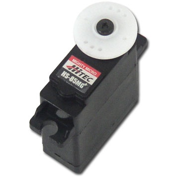
4 x HS85MG Servos chosen for wings. Bought these from Electricwingman as they were doing a deal for 4 servo's. Also purchased Poly C Resin for glassing inside the fuselage and possibly glassing the complete fuselage.
Balsa bulkhead added to stop battery being pushed forward in the event of a nose in landing
Glue longeron onto wing fairing (left & right handed)
Jumping ahead about 10 steps but opportunity to glue fin to rudder post.
Wing fairings glued to the underside of the top planking only
Time to shape the top planking to match the profile of Former No.8
Still more sanding to be done but the rough shape is there
Starting to look like a Phase 6 fuselage
Spent ages sanding and shaping the bottom ply section, still lots to do.....
Next stage is to use my Poly C and light weight glass cloth to glass inside the first two / three sections of the fuselage which should strengthen the fuselage no end. Just need to wait for the Poly C to arrive in the post. I hate having to wait (tick tock tick tock!).
Did I mention that I am impatient?
Hello again, been a while since signing in and lots has happened with the Phase 6 fuselage build. Rather than posting up a whole load of more pictures I thought I would try and do a little bit of video work and to capture more in a shorter while. Let me know what you think?
Phase 6 Build Vlog No.1
Phase 6 Build Vlog No.2
Phase 6 Build Vlog No.3
Would you Adam and Eve it! The lovely wing fairing I had slaved over to shape and get right was sitting on the bench so I thought. Turned around to pick up something turned back around and CRUNCH!! The bloody thing had fallen off the bench and hit the ground so quietly I didn't hear it or know it was there. Broke the thing into multiple pieces. Could have cried. Trying to glue the remains back together. Lesson there for me - Don't be such a clumsy oaf!
Gone is the bent bit of metal that should fit between the tail plane and the elevator and connects the push rod to the elevator. Here you will see the replacement elevator actuator thingy! I have hinged the rudder and the two elevators (splitting one of the elevators - hmm!) Glued the tail plane in place but remember to slide the metal thingy into place before you glue the tail plane into position.
One big problem I have found the tail plane is not horizontal. Its square to the fin (ish..) and is square to the fuselage but look along the now and one side of the tail plane is higher than the other side. How has that happened when all you do is slide the balsa tail plane into the pre cut slot? I have the fuselage in the jig and have rested a huge lump of lead on the high side of the tail plane which has brought it nearly horizontal again. Will this weight help bring it more horizontal, I don't know but I have no idea what to do if this doesn't work. Any suggestions??
Well the fuselage is getting there and the weight on the tail plane does seem to have helped and its looking much more horizontal. The next part you are about to see wasn't done by me. (Tim) kindly offered to set the servo's in the wings and wire them up using Multiplex connectors. He's so much better at this sort of thing than I am. Thanks Tim!!
4 x HS85MG Servos located into the Phase 6 wing. Slots to be cut into the obeche veneer cables fed in next.
More help from Tim. A superb job of locating the servos into the wing. They are glued and then selotaped over the top to make a nice flush wing finish. The slots for the cables have been filled in with balsa strip then sanded and filled - SMOOTH! Servo cables run in slots cut into wing. Balsa strips replacing the obeche that had been removed. Multiplex connectors added. Tim has a nice little gadget that moulds a perfect joint around the bottom of the wires using a hot glue gun. No more loose wires! Can you tell what it is yet ?
Back in the workshop. Time to cut ailerons, flaps and centre section to size.
Had to turn the wing upside down to glue the centre trailing edge into place. Remember the bottom of the wing is flat.
Idiot Mistake No 2: I had spoken with Tim and he suggested I use the finishing resin from Z-poxy that came in exactly the same box as my standard 5 min epoxy (I think you have already guessed my stupid mistake). I was running out of time and thought I would quickly (there you go 'quickly') glass the fibreglass bandage over the already butt jointed wing. Well I grabbed what I thought was the finishing resin and after the top surface was hardening very quickly and was very thick, I put 2 and 2 together and came up with 5 (5 minute Epoxy) DOH DOH DOHHHHHHH!
Well its done now! Get on with it and make the best you can of it.
The top surface wasn't at all bad but the bottom side is a bit like the moon. For some reason my retaining wing nut is far too back in the fuselage. About 15mm from the back edge of the wing. (maybe that's Idiot Mistake No. 3?)
Anyway, Got to make the best of a bad job!
Here is the wing bolted on.
The wing fairing seems to fit over the wing but is well off being flush with the fuselage. I will need to speak with Tim and see where I have gone wrong.
You know I spoke about the tail plane not being horizontal? Well with the wing bolted on the tail plane isn't level compared to the wing. Starting to wish I never started this bloody model now!
New day, new outlook on it all. After a brief flying session up on Itford Hill, we gave up early as it was very windy and very rough. Time to get on with the Phase 6 build.
Added the small plywood patch over the wing bolt hole. This will provide added strength to the whole trailing edge wing bolt area. Time to make the screwdriver hole in the wing fairing and then using 5 minute epoxy I glued the wing fairing onto the wing. A little sanding to get it to sit right on the wing and then some more sanding on top off the fairing to bring the shape inline with the fuselage and hatch. Had the wing bolted up and in position. A little more tweeking is needed to make it just right,
Today, I am happy with the Phase 6.
Most of my idiot decisions and mistakes seem to be recoverable (so far). Can you see the mood is better today?
Tim has worked wonders in getting the tail plane level with the wings. He looked at it from a complete different direction from my way of looking at things. He trimmed the wing support a little that dropped the wing on one side. This brought the wing and the tail plane into horizontal. That's what years of building experience has to offer. He also got the wing to sit on the fuselage a little better.
Today I was working on fitting the flaps and ailerons. Cutting in the hinges using my little hinge cutting tool. One thing to remember this little tool needs a square edge to work and create that perfect hinge cut. I sanded down the aileron and flaps to create a nice 'V' shape before I cut the hinge slots (DOH! another school boy error). Anyway all sorted now...….
Hinge Slotting tool (make sure you cut the hinges when the balsa is still square and not when you have shaped the edge -like I did)
Flaps and ailerons dry fitted but need to be sanded to match the trailing edge and to allow a little more clearance between each other.
Lots of movement with the landing flaps.
Big problems overnight. I was not at all happy with the strength of the balsa provided for the elevators. Just too soft and given the fact you are expected to cut a huge slot in one end to glue in the metal bar that will work the elevator then this makes it just a flimsy thin bit of balsa. So I thought I could use thin glass and Poly C to strengthen up the elevator. Tim had warned me that glassing this thin balsa would make it go like a banana, so I glassed one side and then put a large lump of slightly oiled metal on top and then a big weight on top of that and left it over night. Came in this morning to find the Poly C had stuck to the metal more than the balsa (How does that happen?) and trying to prize them apart resulted in a few fractured bits of Balsa.
Now where do I find a length of trailing edge that is 1/4'' x 1' 1/2'' x 36'' long ?? Anyone got any or knows of a source - PLEASE LET ME KNOW...….
Anyway - Onwards and upwards. Started covering the fuselage. Starting on the bottom.
Made my new elevators today out of much stronger balsa and a little thicker.
It's just the camera, it is orange as above!
The basics covered. Needs some additional flashes of colour because I don't think it is bright enough!! What do you think?
The big change from the conventional Phase 6 here with the addition of landing flaps
Tim is working his magic on the fit out of the model. Servo covers needed to finish of the wing installation.
More Installation Pics - All Tim's work and not mine!
The Phase 6 has been very nicely kitted out by Tim - A huge thanks to him for all his help.
To balance the model with a C of G at 4 1/2'' as detailed within the Instructions you will need to put some nose weight up front. Tim had the simple idea of how to get the nose weight way up front, just cut a hole in the balsa top above the front nose compartment. Fill it with the required lead ballast and glue another lump of balsa on top and sand to shape. Then just add a little more covering and you will be sorted.
The further you go up into the nose the less weight you will need to balance the model. I know with most slope soarers additional weight isn't usually a problem and in some cases like a mouldy I would generally fly with ballast but I would like this Phase 6 to be reasonably light as I don't intend to fly it in a gale but on those light to medium days, so being lighter in this case will be an advantage.
Here are a few more pictures detailing the Installation of the wiring, servo's and Spektrum RX
For easy connectivity - Multiplex connectors
Heavy duty servo's for the fuselage (Hitec HS322HD)
The latest AR620 (6 channel) Spektrum RX
SHE IS FINALLY FINISHED !!!
Just the maiden flight video to come!
Here it is the maiden flight of my new Phase 6 with landing flaps.
The weather was poor with low cloud / mist but the wind felt good. We were flying up on Ditchling Beacon on Sunday 7th April 2019. The model went out of my hand smoothly and needed no clicks of trim in any direction. What a pleasure to fly. Crisp controls in light lift. The landings were very easy with the addition of the landing flaps.
Here's a later video on the same day, with me practising my landings.
I am very happy now. The build was a challenge but the flying was a pleasure!
I think I read a blog somewhere where they ran the servo leads through a groove in the foam under the wing leading/trailing edges, so as to avoid slicing through the veneer.
Funny someone else mentioned this the other day. I always intended to cut veneer as I've got two servo's in each wing. Probably look like a dogs dinner. Thanks for your help and support Russell. Please carry on with the help.
Heroic effort Paul, well done. Have you got the facilities to steam the wood before bending (like a big plastic bag and a wallpaper stripper)? This can make it much softer. I don't like model building without a plan either...
I have bought this battery: Overlander Panasonic Eneloop 2000mAh AA 4.8v Receiver RX Square. My father (Tim) has built a few Phase 6's in his time. Said I should have bought a 5 cell (AA) 6V battery as its slightly heavier.
Whatever battery fits the nose of your model and suits your charger, receiver and servos is good. Eneloop are the most reliable ones I've found. You can fine-tune the ballast with some heavy metal or Plasticine. The nose cone of my latest glider carries six 2p coins... Tim has a valid point though. If a five-cell NiMh will fit and you know you will need the extra ballast anyway, then it offers a neat solution. There is also the theoretical benefit of a 6V supply making the servos fractionally faster and more powerful. My only concern would be whether my favourite Tx/Rx charger is able to charge a 6V pack instead of the regular 4.8V pack.
Thanks for the replies I have the 6v 5 cell overlander 2000 mah so sounds like im on the right lines . I glassed in a bulkhead in front of it in the nose as the instructions to prevent it splitting the nose in the event of a bad landing . Toying with making a forward removable hatch to enable battery and ballast accessability . Also need to check my small prolux 2114F will charge up the 6v battery . looking forward to seeing your wing servo set up .
Great progress Paul. I envy you having the opportunity to spend every day building a glider. Sensible choice of resin - I'm still using up the tin of polyurethane floor varnish I bought for the bathroom cork tiles ten years ago. Top-notch servos too.
Good Vlogs Paul, very clear and concise. I admire your confidence in reinforcing the wing retaining plate over the captive nut. Obviously an expert RC pilot like yourself need not worry about crash landings. For a nervous flyer like me, I'd stick to a thin ply plate and carry a couple of spares to the slope - it's easier to fix than a torn off wing...
Thanks Russell. I am still hoping that the plastic bolt will break on the inevitable poor landing or when the ground leaps up and catches your model. The ply plate was to keep the wing retaining nut in place and the bolt fixes in exactly the same spot as dictated by CF.
From reading a build on a forum, a guy did the same as Paul, but to create a week/give way point, he drilled down the centre of the plastic wing bolt so it would shear easily if needed.
Hi Russell. No. I meant the bottom of the wing is flat and turning the wing upside down you can use a ruler to get the centre trailing edge flush. If that makes sense.
Just building one of these so took a look at this blog. For the benefit of anyone else doing similar, as per the instructions, the top surface of the wing should be flat not the bottom.
Hi Pete. Not sure in what context your comment is taken. I don't want to assume you mean when the Phase 6 is built the flat surface of the wing should be at the top as we all know the flat section is on the bottom on the sport wing. You must mean something different??
Hi, I did not anticipate that my comments would start a discussion, I was merely stating the correct build step. This difference of opinion must be down to terminology. Please do assume that the (top, cambered) surface of the wing halves (laterally) when being joined together should be flat on a building board. Because of the taper towards the wing tip this will impart a small element of required dihedral. This is valid for both the Sport and Professional wings. I refer to the Phase 6 instruction sheet from Chris Foss Page 3, Step 3 "Using 5 min. epoxy, glue panels together, laying upside down on flat surface. Thickness taper of wing will automatically give slight dihedral required", this together with my 45 years of RC model building and flying experience. I confirm that this is solely regarding the joining of the two wing halves. Hopefully this clarifies any misconception.
Yes, I dont think that we are on the same page. When the two halves of the wing are stuck together they should be joined on a flat surface with the top, cambered, surface of the wing facing downwards. This then results in a wing that is flat, tip to tip, on the upper surface but with slight dihedral on the lower surface provided by the taper in the wing because of the different thickness between the root and the tip. This is described by C Foss in the instruction sheet. Page 3 (wing) step 3.
How do you intend to cover your wing servos ? and any issues with having connectors buried in the wings are the connections between servos and the Y lead just standard ? Thanks
Plywood servo covers. No issues with cables buried in the wings on other models. No use of Y leads. All servoes independent - R & L Ailerons and landing flap.
Hi Paul, does the 6 channel spektrum receiver allow independent flaps and ailerons? I dont fly spektrum myself but my son does. With Futaba, i have to use a 7 channel receiver.
Brilliant thread! I love the Phase 6 and this will really help with my build, thank you! I'm hoping to come and fly with you guys soon, maybe when these storms have passed though... looking forward to meeting you all.
Thanks for the great blog. I dug my 25 year old middle phase out I so enjoyed flying it again I've got a phase 6 kit I will add flaps as you have the landings were impressive!. Thinking of covering in tissue and dope same as the old middle phase . If only I could work out a way to fit it on my motorbike to take to Cornwall..


I think I read a blog somewhere where they ran the servo leads through a groove in the foam under the wing leading/trailing edges, so as to avoid slicing through the veneer.
ReplyDeleteFunny someone else mentioned this the other day. I always intended to cut veneer as I've got two servo's in each wing. Probably look like a dogs dinner. Thanks for your help and support Russell. Please carry on with the help.
ReplyDeleteHeroic effort Paul, well done. Have you got the facilities to steam the wood before bending (like a big plastic bag and a wallpaper stripper)? This can make it much softer.
ReplyDeleteI don't like model building without a plan either...
Great Blog ...What size battery have you gone for ?
ReplyDeleteGreat Blog , Im currently building a phase 6
ReplyDeleteWhat size battery did you go for ?
I have bought this battery: Overlander Panasonic Eneloop 2000mAh AA 4.8v Receiver RX Square. My father (Tim) has built a few Phase 6's in his time. Said I should have bought a 5 cell (AA) 6V battery as its slightly heavier.
ReplyDeleteThis comment has been removed by the author.
DeleteWhatever battery fits the nose of your model and suits your charger, receiver and servos is good. Eneloop are the most reliable ones I've found. You can fine-tune the ballast with some heavy metal or Plasticine. The nose cone of my latest glider carries six 2p coins...
ReplyDeleteTim has a valid point though. If a five-cell NiMh will fit and you know you will need the extra ballast anyway, then it offers a neat solution. There is also the theoretical benefit of a 6V supply making the servos fractionally faster and more powerful. My only concern would be whether my favourite Tx/Rx charger is able to charge a 6V pack instead of the regular 4.8V pack.
Thanks for the replies
ReplyDeleteI have the 6v 5 cell overlander 2000 mah so sounds like im on the right lines . I glassed in a bulkhead in front of it in the nose as the instructions to prevent it splitting the nose in the event of a bad landing . Toying with making a forward removable hatch to enable battery and ballast accessability .
Also need to check my small prolux 2114F will charge up the 6v battery .
looking forward to seeing your wing servo set up .
Great progress Paul. I envy you having the opportunity to spend every day building a glider.
ReplyDeleteSensible choice of resin - I'm still using up the tin of polyurethane floor varnish I bought for the bathroom cork tiles ten years ago. Top-notch servos too.
Good Vlogs Paul, very clear and concise. I admire your confidence in reinforcing the wing retaining plate over the captive nut. Obviously an expert RC pilot like yourself need not worry about crash landings. For a nervous flyer like me, I'd stick to a thin ply plate and carry a couple of spares to the slope - it's easier to fix than a torn off wing...
ReplyDeleteThanks Russell. I am still hoping that the plastic bolt will break on the inevitable poor landing or when the ground leaps up and catches your model. The ply plate was to keep the wing retaining nut in place and the bolt fixes in exactly the same spot as dictated by CF.
ReplyDeleteFrom reading a build on a forum, a guy did the same as Paul, but to create a week/give way point, he drilled down the centre of the plastic wing bolt so it would shear easily if needed.
ReplyDeleteIt is looking cool Paul. Well done you and Tim (neat work on those Multiplex connectors). Did you mean that the TOP of the wing is flat?
ReplyDeleteHi Russell. No. I meant the bottom of the wing is flat and turning the wing upside down you can use a ruler to get the centre trailing edge flush. If that makes sense.
ReplyDeleteJust building one of these so took a look at this blog. For the benefit of anyone else doing similar, as per the instructions, the top surface of the wing should be flat not the bottom.
DeleteHi Pete. Not sure in what context your comment is taken. I don't want to assume you mean when the Phase 6 is built the flat surface of the wing should be at the top as we all know the flat section is on the bottom on the sport wing. You must mean something different??
DeleteHi, I did not anticipate that my comments would start a discussion, I was merely stating the correct build step. This difference of opinion must be down to terminology. Please do assume that the (top, cambered) surface of the wing halves (laterally) when being joined together should be flat on a building board. Because of the taper towards the wing tip this will impart a small element of required dihedral. This is valid for both the Sport and Professional wings. I refer to the Phase 6 instruction sheet from Chris Foss Page 3, Step 3 "Using 5 min. epoxy, glue panels together, laying upside down on flat surface. Thickness taper of wing will automatically give slight dihedral required", this together with my 45 years of RC model building and flying experience.
DeleteI confirm that this is solely regarding the joining of the two wing halves.
Hopefully this clarifies any misconception.
Yes, I dont think that we are on the same page. When the two halves of the wing are stuck together they should be joined on a flat surface with the top, cambered, surface of the wing facing downwards. This then results in a wing that is flat, tip to tip, on the upper surface but with slight dihedral on the lower surface provided by the taper in the wing because of the different thickness between the root and the tip.
DeleteThis is described by C Foss in the instruction sheet. Page 3 (wing) step 3.
Thank you Pete for your input. I hope you have enjoyed looking at our blog?
DeleteYes, a good site. Before moving West I lived in West Sussex for 30+ years so I am familiar with many of the places that you fly.
DeleteHow do you intend to cover your wing servos ? and any issues with having connectors buried in the wings are the connections between servos and the Y lead just standard ?
ReplyDeleteThanks
Plywood servo covers. No issues with cables buried in the wings on other models. No use of Y leads. All servoes independent - R & L Ailerons and landing flap.
ReplyDeleteHi Paul, does the 6 channel spektrum receiver allow independent flaps and ailerons? I dont fly spektrum myself but my son does. With Futaba, i have to use a 7 channel receiver.
DeleteIt looks very bright and cheerful Paul. Are you going to add contrasting colours, top and bottom, to aid orientation?
ReplyDeleteYes I am Russell, just waiting for some Solartrim so I can put some contrasting stripes on both flying surfaces.
ReplyDeleteGreat, it's always good to have a clear visual prompt as to which way is up.
ReplyDeleteIt's looking really good . What painting system did you use to get such a good finish ?
ReplyDeleteThe model is covered with heat shrink film called Solarfilm. No paint used.
ReplyDeleteHi I am no builder but this is very helpful
ReplyDeleteTHANK YOU
Brilliant thread! I love the Phase 6 and this will really help with my build, thank you! I'm hoping to come and fly with you guys soon, maybe when these storms have passed though... looking forward to meeting you all.
ReplyDeleteThanks for the great blog. I dug my 25 year old middle phase out I so enjoyed flying it again I've got a phase 6 kit
ReplyDeleteI will add flaps as you have the landings were impressive!.
Thinking of covering in tissue and dope same as the old middle phase .
If only I could work out a way to fit it on my motorbike to take to Cornwall..